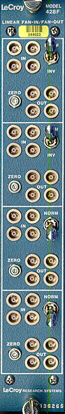
LeCroy 428F Quad Linear Fan-In/Fan-Out
OVERVIEW
FEATURES
- Four Independent Sections with 4 Inputs per Section
- Positive or Negative Inputs
- Each Section has 4 Outputs
- High Rate: DC to 100 MHz
- NIM Packaging
DESCRIPTION
The LeCroy Model 428F Quad Linear Fan-In/Fan-Out combines the
functions of two previously separate LeCroy linear circuits
in one compact unit.
Each channel/section of the Model 428F Quad Linear Fan-In/Fan-Out
contains 4 direct-coupled linear bipolar inputs, a polarity inversion
switch, and four direct-coupled linear outputs.
The bipolar inputs, together with the polarity switch, allow convenient
summing of either anode or dynode pulses. An output swing of +100 mV
to -2 V is compatible with all normal analog inputs (e.g., discriminators,
ADCs, etc.) and also accommodates standard logic levels. Each of the
Model 428F's inputs is provided with input protection circuitry which
gives immunity to transient signals up to +/-5 A for 0.5 microseconds.
The incorporation of the polarity switch is particularly significant
in that it enables convenient, direct use of the fanned-out dynode
signals for multiple fast logic decisions, while the anode signal
can be directly applied to a current-integrating ADC.
All outputs are reverse-terminated and mutually isolated.
The Model 428F utilizes a direct-coupled feedback-stabilized circuit
design that provides excellent linearity, long-term stability,
and uniformity of gain and pulse shape. The speed of the unit
is suitable for all common photomultiplier and logic signals,
and there are no duty cycle limitations or rate effects in the
Normal Mode.
In the Inverting Mode, the Model 428F operates as a
capacitively-coupled unit with a 400 µsec time constant,
recovering to the average non-inverted DC input level.
In addition, the Model 428F exhibits duty-factor related
baseline shifts equal to twice that of a normal AC-coupled circuit.
Thus, although the Inverting Mode provides great versatility and
convenience in application, some care must be exercised when using
this mode with wide inputs or at high rates.
The Model 428F is packaged in a standard NIM #1 width module
and utilizes +/-12 V, +/-24 V at little enough current to permit
the use of 12 modules (48 channels) in a standard NIM power bin.
SPECIFICATIONS
- Number of Sections:
- Four independent sections with 4 inputs per section.
A front-panel switch on each section which selects
normal or inverting mode.
Input Characteristics
Number of Channels:
Four.
Number of Inputs:
4 per channel; 50 Ohm +/-5%;
direct-coupled in non-inverting mode.
In inverting mode operates as a capacitively-coupled
unit with a 400 µsec time constant.
Polarity:
Positive or Negative analog signals.
Reflection Coefficient:
Less than 7% for inputs of 2 nsec risetime.
Input Protection:
Inputs protected against 0.5 µsec transient overloads,
up to +/- 5 A.
Output Characteristics
Number of Outputs:
4 per channel; reverse-terminated;
direct-coupled; for optimum output shape,
three outputs must be terminated into 50 Ohm.
For proper operation, at least 2 outputs must be
terminated on each channel used.
Integral Non-Linearity:
+/- 1% up to - 1 Volt.
Linear Range:
Normal Mode: + 100 mV to > - 2 Volts.
Inverting Mode: +100 mV to > -1.5 Volts.
Maximum Amplitude:
Normal Mode: > -2.0 Volts into 50 Ohm.
Inverting Mode: > -1.5 Volts into 50 Ohm.
Gain:
Normal Mode: 1.0 +/- 2% up to -2 Volts.
Inverting Mode: Approximately 0.98 up to -1.5 Volts.
Rise Times:
2.5 nsec, 10% to 90%, with outputs terminated in 50 Ohm.
Fall Times:
4 nsec 10% to 90%, with outputs terminated in 50 Ohm.
DC Offset:
Adjustable with front-panel potentiometer.
Care should be taken to readjust DC level
whenever the Normal/Inverting switch is used.
DC Offset Stability:
< 60 µV/°C in normal and inverting modes.
Output DC Level Voltage Coefficient:
< 25 µV/1% variation of any supply voltage
in normal and inverting modes.
Interchannel Isolation:
40 dB.
Noise:
< 750 µV R.M.S.
Output Delay:
< 6 nsec.
Overload Recovery:
Approximately 2 nsec with four simultaneous NIM level (-800 mV) inputs.
GENERAL
Rate:
DC to 100 MHz typically.
Input/Output Delay:
< 6 nsec.
Duty Cycle Limitations:
None for direct-coupled outputs.
Polarity Inversion:
A front-panel switch on each channel selects
normal or inverting operation.
Packaging:
RF-shielded AEC/NIM #1 module;
Dimensions 1.375 x 8.75 x 10 inches deep;
Lemo-type connectors.
Power Requirements:
+24 V at 80 mA, - 24 V at 80 mA,
+12 V at 160 mA, -12 V at 160 mA.